Why CAN Bus Support (J1939/OBD-II) Is Essential for Fleet MDTs
CAN bus support is essential when a fleet mobile data terminal must do more than display routes and messages: it connects the application to vehicle operating data for engine-aware workflows, maintenance triage, and compatible ELD implementations. But a CAN port alone is not enough. A dependable fleet MDT needs the correct protocol stack, vehicle access, decoding software, electrical integration, and data-quality controls. The real buying criterion is interoperability—not simply the presence of a connector.
CAN provides the communication foundation. J1939 defines heavy-duty vehicle messaging. OBD-II provides standardized diagnostic access within a regulated scope. These terms are related, but they are not interchangeable.
CAN bus, J1939, and OBD-II: what is the difference?
A mobile data terminal, or MDT, is the vehicle-side computing interface used for tasks such as dispatch, inspections, routing, and driver communication. Connecting it to vehicle data can turn a generic screen into a context-aware fleet terminal.
CAN, short for Controller Area Network, carries messages between electronic control units. It does not, by itself, tell your application which bytes represent engine speed or how a diagnostic request should work.
SAE J1939 is a family of standards widely used in heavy-duty vehicles. It defines message organization and signal interpretation above CAN. OBD-II is an onboard diagnostics framework associated with standardized diagnostic services; it can use CAN, but older implementations also use other communication protocols.
Technical basis: CAN bus introduction; SAE, OBD standards overview.
J1939 vs. OBD-II for fleet management terminals
| Question | J1939 integration | OBD-II integration |
|---|---|---|
| Where is it commonly relevant? | Heavy-duty trucks, buses, and many off-highway machines | Passenger vehicles, light-duty fleets, and other vehicles within applicable OBD requirements |
| How is data identified? | Parameter Group Numbers, or PGNs, organize messages; Suspect Parameter Numbers, or SPNs, identify parameters | Diagnostic services and parameter identifiers; supported data depends on the vehicle and diagnostic implementation |
| How is data acquired? | Some messages are broadcast; other information requires requests and protocol handling | Many common diagnostic workflows use a request-and-response model |
| What does it not guarantee? | Access to every OEM signal, every network segment, or every proprietary parameter | Universal access to total odometer, lifetime engine hours, battery health, or all manufacturer-specific data |
| What should the supplier prove? | Required PGNs/SPNs, supported network configuration, request behavior, and decoding accuracy | Required services, supported parameters, transport compatibility, and gateway access |
Protocol references: J1939 message and parameter structure; SAE, diagnostic standards and emissions-related scope.
What CAN-connected fleet MDTs can enable
The following are practical application patterns—not guaranteed outcomes. Each depends on available signals, validated decoding, and a workflow that turns information into action.
Engine-aware operations
Combine an available engine-running signal with vehicle speed and task context to distinguish travel, waiting, and possible idling. Define the thresholds explicitly so stationary work is not automatically classified as waste.
Maintenance triage
Associate available fault information with vehicle identity, timestamps, and operator observations. A fault code can help prioritize investigation; it does not independently identify the failed component.
Better workflow context
Use validated vehicle state to support application rules, inspection prompts, and event records. Keep convenience automation separate from safety-critical control unless the complete system is engineered for that purpose.
Avoid promising a universal fuel-saving percentage or guaranteed downtime reduction. A credible business case starts with a fleet baseline, verified signal availability, and measured operational changes during a controlled pilot.
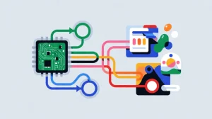
From raw CAN frames to trustworthy fleet data
or gateway
& validation
& fleet platform
Decoding is a deliverable—not an assumption
Raw CAN access gives software message identifiers and payload bytes. A J1939 decoder must interpret the correct message structure and apply the parameter definitions, including scale, offset, units, and validity handling.
CSS Electronics explains that J1939 PGNs organize parameters and that SPN definitions describe information such as bit position, length, scale, and offset. This is why “CAN supported” and “engine data available in our Android app” are different claims.
Decoding reference: J1939 PGNs, SPNs, and signal interpretation.
Specify an application-ready data contract
- Signal name, source, units, and supported vehicle configuration.
- Timestamp, freshness limit, and expected availability.
- Explicit handling for invalid, unsupported, and stale values.
- Local buffering and duplicate-safe synchronization behavior.
- SDK version, sample code, licensing, and update ownership.
An unavailable signal is not a zero
For a rugged Android tablet with CAN bus, data quality matters as much as connection uptime. A cached speed value must not appear live after the vehicle interface disconnects. An unsupported fuel parameter must not become a zero-consumption record.
Require the application to distinguish “valid,” “stale,” “unavailable,” and “not supported.” Test these states deliberately by interrupting the interface, cycling ignition, and removing network coverage.
Keep two failures distinct: loss of vehicle data and loss of the cloud connection. Local acquisition may continue during a cellular outage, while a working cellular link cannot repair a disconnected vehicle interface.
CAN bus and ELD integration: necessary data access is not complete compliance
For U.S. electronic logging device implementations, engine synchronization is a defined requirement. FMCSA identifies four engine-related elements: engine power status, vehicle motion status, miles driven, and engine hours.
“An ELD must be integrally synchronized with the engine of the commercial motor vehicle (CMV).”
FMCSA, ELD Functions FAQs.
A J1939-capable MDT or OBD-II connection can support the data-acquisition architecture, but neither makes a tablet a compliant ELD by itself. Evaluate the complete ELD implementation, its required functions, and the provider’s certification and registration status rather than treating a hardware interface as regulatory approval.
Regulatory context: FMCSA: About ELDs and the provider process.
Integrated CAN MDT or external vehicle gateway?
| Design question | CAN integrated into the MDT | Separate gateway plus MDT |
|---|---|---|
| Where does vehicle acquisition run? | Within the terminal or its integrated interface subsystem | In a dedicated gateway that forwards data to the terminal or platform |
| What should you evaluate? | SDK maturity, terminal uptime, firmware control, and harness serviceability | Gateway protocol coverage, link recovery, independent buffering, and version compatibility |
| What happens when the display is removed? | Acquisition continuity must be explicitly verified | Independent acquisition may be possible if the gateway is designed and powered for it |
| What is the decision rule? | Choose when the integrated system meets acquisition and service requirements with fewer components | Choose when independent collection, specialist protocols, or replaceable display hardware justify the extra component |
This is an engineering trade-off framework, not a claim that one architecture is universally more reliable.
Installation details that decide deployment quality
- Use an OEM-approved connection point and vehicle-specific pinout. Do not assume identical connectors expose identical networks.
- Verify bit rate, supported frame formats, and any required CAN FD capability. Classical CAN support does not establish CAN FD support.
- Follow the approved topology and termination design. Do not automatically add a termination resistor to an already terminated vehicle network.
- Ask whether isolation, transient protection, and grounding meet the installation requirements. A nominal DC input range does not prove immunity to all vehicle electrical disturbances.
- Minimize unnecessary transmission. Receiving broadcast frames and sending diagnostic requests are different operations; define permitted requests, rates, and access controls.
- Restrict firmware and application access to vehicle transmission functions. Do not expose unrestricted raw CAN commands through a cloud-facing application.
Background on CAN wiring, termination, and protocol distinctions: CSS Electronics CAN bus technical introduction.
Rugged vehicle tablets to evaluate for CAN-connected fleet applications
Use these platforms as hardware candidates, then validate the exact interface configuration and software scope. The specifications below are manufacturer-published, not independent interoperability certifications.
WAYSION Q777
Android 14 / RK3568 / IP65The Q777 product page lists a built-in CAN interface, vehicle-oriented I/O, docking support, and 9–36 V input. Its FAQ describes J1939-based integration according to project requirements.
For a heavy-duty fleet MDT project, request the supported PGNs/SPNs, Android API documentation, sample application, harness definition, and target-vehicle test results. Confirm whether OBD-II decoding is supplied natively, through middleware, or through an external interface. [csselectronics](https://www.csselectronics.com/pages/j1939-explained-simple-intro-tutorial)
Explore Q777 vehicle tablet specifications →WAYSION Mars 876
Android 15 / RK3576 / IP65Mars 876 lists CAN, Ethernet, serial interfaces, GPIO, and AHD camera integration options, alongside 9–36 V DC input. It is a candidate when vehicle data must share an operator interface with additional peripherals.
The CAN interface does not independently establish complete J1939 or OBD-II application coverage. Request the protocol implementation scope, available SDK, interface options, and a workload test using the intended fleet software. [eld.fmcsa.dot](https://eld.fmcsa.dot.gov/FAQ/SearchFAQs?searchWord=Motion)
Explore Mars 876 vehicle terminal specifications →Five tests before deploying a fleet MDT with J1939 or OBD-II
- Build a vehicle-and-signal compatibility matrix
List each relevant vehicle configuration, required signal, access method, update requirement, and supported application function. Mark unsupported signals before commercial commitment.
- Compare decoded values with a trusted reference
Validate units, scaling, timestamps, source selection, and invalid-value behavior using an approved diagnostic tool or engineering reference.
- Test power transitions and reconnection
Exercise ignition on/off, cranking, terminal restart, dock removal where applicable, and interface interruption. Confirm automatic recovery without silently reusing stale data.
- Test cloud outages separately
Remove WAN coverage while vehicle acquisition continues. Verify local timestamps, storage limits, event ordering, retries, and duplicate handling after reconnection.
- Demonstrate service and update recovery
Replace a terminal, restore its configuration, apply an approved software update, and verify vehicle data again. Document responsibilities across the hardware supplier, protocol vendor, and fleet application provider.
CAN bus fleet MDT FAQ
Does a built-in CAN port guarantee J1939 support?
No. It establishes a hardware communication capability, not a complete protocol implementation. J1939 integration also requires the appropriate message handling and parameter decoding. Ask which PGNs and SPNs are supported in the delivered software.
Are CAN bus and OBD-II the same thing?
No. CAN is a communication technology; OBD-II concerns standardized onboard diagnostic access and services. OBD can operate over CAN, but other transports exist. A CAN interface alone is not a complete OBD-II diagnostic implementation.
Can a CAN-connected tablet read every vehicle parameter?
Do not assume so. Confirm each required signal against the specific vehicle, accessible network, protocol implementation, and decoder. Standardized messaging does not make every manufacturer-specific parameter available.
Does a fleet MDT need built-in CAN if it already uses a gateway?
Not necessarily. A gateway can acquire and decode vehicle information, while the MDT receives application-ready data. Validate the gateway-to-terminal link, timestamps, loss-of-connection behavior, and acquisition continuity before deciding whether integrated CAN adds value.
Does J1939 or OBD-II support make a rugged tablet ELD-compliant?
No. Vehicle data access supports engine synchronization, but compliance applies to the complete ELD implementation and its required functions. Review the ELD provider’s certification and registration, not just the tablet datasheet.
Tags: CAN bus integration for fleet management, J1939 fleet management tablet, OBD2 tablet for fleet management, rugged tablet with CAN bus, vehicle mounted tablet with CAN Bus